✓ Board-verified
Physics · 2026 · 4 marks
CBSE 2026 · Region 3 · Set 1 · Q29
Capacitors are manufactured with certain standard capacitances and working voltages. However, these standard values may not be the ones that are…
Capacitors are manufactured with certain standard capacitances and working voltages. However, these standard values may not be the ones that are actually needed in a particular application. Two or more capacitors can be grouped in series or in parallel to achieve desired capacitance and voltage. When connected in series, the total capacitance decreases while the voltage rating increases, whereas in parallel connections, the total capacitance increases and maintains the same voltage rating. A capacitor stores energy in the electric field between its plates and stored energy is proportional to the square of the voltage and capacitance $\displaystyle \mathrm{U}=\frac{1}{2} \mathrm{CV}^{2}$, where symbols have their usual meanings.
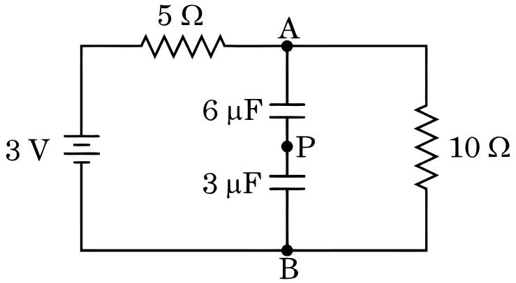
Two capacitors, one of $\displaystyle 3 \mu \mathrm{~F}$ and the other of $\displaystyle 6 \mu \mathrm{~F}$, are connected in series in the circuit as shown in the figure, for a long time.
(i)
The total capacitance of the circuit is :
(A)
$\displaystyle 6 \mu \mathrm{~F}$
(B)
$\displaystyle 3 \mu \mathrm{~F}$
(C)
$\displaystyle 9 \mu \mathrm{~F}$
(D)
$\displaystyle 2 \mu \mathrm{~F}$
(ii)
The current in the $\displaystyle 10 \Omega$ resistor is :
(A)
$\displaystyle 0 \cdot 3 \mathrm{~A}$
(B)
0.$\displaystyle 6$ A
(C)
$\displaystyle 0 \cdot 2 \mathrm{~A}$
(D)
$\displaystyle 0$
(iii) The potential difference between point A and B is :
(A)
$\displaystyle 2$ V
(B)
0.$\displaystyle 3$ V
(C)
$\displaystyle 0 \cdot 2 \mathrm{~V}$
(D)
$\displaystyle 3$ V
(iv)
(a)
The value of charge on the plates of the $\displaystyle 6 \mu \mathrm{~F}$ capacitor is :
(A)
$\displaystyle 6 \mu \mathrm{C}$
(B)
$\displaystyle 4 \mu \mathrm{C}$
(C)
$\displaystyle 12 \mu \mathrm{C}$
(D)
$\displaystyle 8 \mu \mathrm{C}$
OR
(b)
The wire between two capacitors is cut at point P. The current in the circuit will :
(A)
increase
(B)
decrease
(C)
remain the same
(D)
first increase then become stable
Marking-scheme solution
(i)(D)
$\displaystyle 2\ \mu \mathrm{F}$
(ii)(C)
0.$\displaystyle 2$ A
(iii)(A)
$\displaystyle 2$ V
(iv)(a)
(B) $\displaystyle 4\ \mu \mathrm{C}$ OR (b) (C) remain the same
All Electrostatic Potential and Capacitance questions2026 question paperNCERT solutions: Electrostatic Potential and CapacitancePractice Electrostatic Potential and Capacitance →
More from Electrostatic Potential and Capacitance
- (i) A parallel plate capacitor with plate area A and plate separation d has a capacitance C_0. A slab of dielectric constant K having area A and…2025
- (i) In the figure, OA and OB show the variation of electric potential V at a point due to two point charges Q_1 and Q_2 with 1/r respectively. Here r…2026
- A point charge q_0 is moving along a circular path of radius a, with a point charge -Q at the centre of the circle. The kinetic energy of q_0 is2023
- The effective capacitance of the network between points A and B shown in the figure is:2025
- Two metal spheres of radii r_1 and r_2(>r_1) having charges q_1 and q_2 respectively kept in air, are brought in contact. Which of the following…2026
- (i) Explain the following statements giving reason: (I) An equipotential surface through a point is normal to the electric field at that point. (II)…2026
- A parallel plate capacitor has plate area A and plate separation d. Half of the space between the plates is filled with a material of dielectric…2025
- A thin spherical conducting shell of radius R has a charge q. A point charge Q is placed at the centre of the shell. Find (i) the charge density on…2024
CBSE Class 12 Physics past-paper question from the 2026 board exam, with the answer as CBSE’s own marking scheme gives it. Where our answers come from.