✓ Board-verified
Physics · 2025 · 4 marks
CBSE 2025 · Region 6 · Set 1 · Q29
A capacitor is a system of two conductors separated by an insulator. In practice, the two conductors have charges Q and -Q with potential difference…
A capacitor is a system of two conductors separated by an insulator. In practice, the two conductors have charges Q and -Q with potential difference $\displaystyle \mathrm{V}=\mathrm{V}_{1}-\mathrm{V}_{2}$ between them. The ratio $\displaystyle \frac{\mathrm{Q}}{\mathrm{V}}$ is a constant, denoted by $\displaystyle \mathrm{C}$ and is called the capacitance of the capacitor. It is independent of Q or V. It depends only on the geometrical configuration (shape, size, separation) of the two conductors and the medium separating the conductors. When a parallel plate capacitor is charged, the electric field $\displaystyle \mathrm{E}_{0}$ is localised between the plates and is uniform throughout. When a slab of a dielectric is inserted between the charged plates (charge density $\displaystyle \sigma$ ) , the dielectric is polarised by the field. Consequently opposite charges appear on the faces of the slab, near the plates, with surface charge density of magnitude $\displaystyle \sigma_{\mathrm{p}}$. For a linear dielectric $\displaystyle \sigma_{\mathrm{p}}$ is proportional to $\displaystyle \mathrm{E}_{0}$. Introduction of a dielectric changes the electric field, and hence, the capacitance of a capacitor, and hence, the energy stored in the capacitor. Like resistors, capacitors can also be arranged in series or in parallel or in a combination of series and parallel.
(i)
Consider a capacitor of capacitance C, with plate area A and plate separation d, filled with air[Fig. (a) ]. The distance between the plates is increased to $\displaystyle 2$ d and one of the plates is shifted as shown in Fig. (b) . The capacitance of the new system now is:
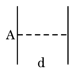
(a)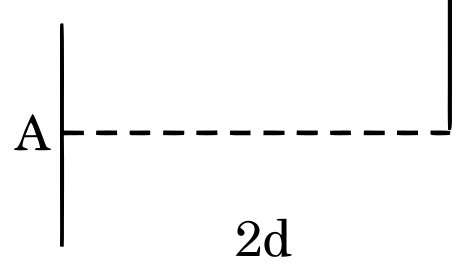
(A)
$\displaystyle \frac{\mathrm{C}}{4}$
(B)
$\displaystyle \frac{\mathrm{C}}{2}$
(C)
$\displaystyle 2$ C
(D)
$\displaystyle 4$ C
(ii)
A slab (area A and thickness $\displaystyle \mathrm{d}_{1}$ ) of a linear dielectric of dielectric constant K is inserted between charged plates (charge density $\displaystyle \sigma$ ) of a parallel plate capacitor [plate area A and plate separation $\displaystyle \left.\mathrm{d}\left(>\mathrm{d}_{1}\right)\right]$ and opposite charges with charge density of magnitude $\displaystyle \sigma_{\mathrm{p}}$ appear on the faces of the slab. The dielectric constant K is given by :
(A)
$\displaystyle \frac{\sigma+\sigma_{\mathrm{p}}}{\sigma}$
(B)
$\displaystyle \frac{\sigma}{\sigma-\sigma_{\mathrm{p}}}$
(C)
$\displaystyle \frac{\sigma+\sigma_{\mathrm{p}}}{\sigma_{\mathrm{p}}}$
(D)
$\displaystyle \frac{\sigma}{\sigma_{\mathrm{p}}}$
(iii)
An electric field E is established between the plates of an air filled parallel plate capacitor, with charges Q and $\displaystyle -\mathrm{Q} . \mathrm{V}$ is the volume of the space enclosed between the plates. The energy stored in the capacitor is :
(A)
$\displaystyle \frac{1}{2} \varepsilon_{0} \mathrm{E}^{2}$
(B)
$\displaystyle \varepsilon_{0} \mathrm{Q}^{2} \mathrm{E}$
(C)
$\displaystyle \frac{1}{2} \varepsilon_{0} \mathrm{E}^{2} \mathrm{~V}$
(D)
$\displaystyle \varepsilon_{0} \mathrm{EQV}$
(iv)(a)
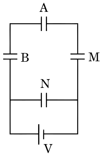
Three capacitors A, B and M, each of capacitance C are connected to a capacitor N of capacitance $\displaystyle 2$ C and a battery as shown in the figure. If the charges on A and N are Q and $\displaystyle \mathrm{Q}^{\prime}$ respectively, then $\displaystyle \frac{\mathrm{Q}^{\prime}}{\mathrm{Q}}$ is :
(A)
$\displaystyle \frac{1}{6}$
(B)
$\displaystyle \frac{1}{3}$
(C)
$\displaystyle 3$
(D) $\displaystyle 6$
A slab (area A and thickness $\displaystyle \frac{\mathrm{d}}{2}$ ) of dielectric constant K is inserted in a parallel plate capacitor of plate area A and plate separation d . If C and $\displaystyle \mathrm{C}_{0}$ are the capacitances of the capacitors with and without the dielectric, then $\displaystyle \frac{\mathrm{C}}{\mathrm{C}_{0}}$ is :
(A)
$\displaystyle \frac{\mathrm{K}+1}{2 \mathrm{~K}}$
(B)
$\displaystyle \frac{2 \mathrm{~K}}{\mathrm{~K}+1}$
(C)
$\displaystyle \frac{\mathrm{K}}{\mathrm{K}-1}$
(D)
$\displaystyle \frac{\mathrm{K}-1}{\mathrm{~K}}$
Marking-scheme solution
(i) (A) \(\displaystyle \left(\frac{\mathrm{C}}{4}\right)\)
(ii) (B) \(\displaystyle \frac{\sigma}{\sigma-\sigma_{\mathrm{p}}}\)
(iii) (C) \(\displaystyle \frac{1}{2} \varepsilon_{0} \mathrm{E}^{2} \mathrm{V}\)
(iv) (a) (D) $\displaystyle 6$ OR
(b) (B) \(\displaystyle \frac{2 \mathrm{K}}{\mathrm{K}+1}\)
All Electrostatic Potential and Capacitance questions2025 question paperNCERT solutions: Electrostatic Potential and CapacitancePractice Electrostatic Potential and Capacitance →
More from Electrostatic Potential and Capacitance
- (i) A parallel plate capacitor with plate area A and plate separation d has a capacitance C_0. A slab of dielectric constant K having area A and…2025
- (i) In the figure, OA and OB show the variation of electric potential V at a point due to two point charges Q_1 and Q_2 with 1/r respectively. Here r…2026
- A point charge q_0 is moving along a circular path of radius a, with a point charge -Q at the centre of the circle. The kinetic energy of q_0 is2023
- The effective capacitance of the network between points A and B shown in the figure is:2025
- Two metal spheres of radii r_1 and r_2(>r_1) having charges q_1 and q_2 respectively kept in air, are brought in contact. Which of the following…2026
- (i) Explain the following statements giving reason: (I) An equipotential surface through a point is normal to the electric field at that point. (II)…2026
- A parallel plate capacitor has plate area A and plate separation d. Half of the space between the plates is filled with a material of dielectric…2025
- A thin spherical conducting shell of radius R has a charge q. A point charge Q is placed at the centre of the shell. Find (i) the charge density on…2024
CBSE Class 12 Physics past-paper question from the 2025 board exam, with the answer as CBSE’s own marking scheme gives it. Where our answers come from.