✓ Board-verified
Physics · 2026 · 5 marks
CBSE 2026 · Region 2 · Set 1 · Q33
(a) A series combination of L, C and R is connected to an a.c. source. Using a phasor diagram, derive an expression for the impedance of the circuit…
(a)
A series combination of L, C and R is connected to an a.c. source. Using a phasor diagram, derive an expression for the impedance of the circuit and phase difference between V and I.
(b)
Under what conditions the
(i)
impedance of the circuit is minimum ?
(ii)
Wattless current flows in the circuit ?
OR
(i)
With the help of a labelled diagram, explain the principle, construction and working of an a.c. generator.
(ii)
Deduce an expression for the induced emf in the coil of the generator.
(iii)
If T is the time period of the rotation of the coil, at what values of T in a cycle, the emf generator is maximum ?
Marking-scheme solution
(a)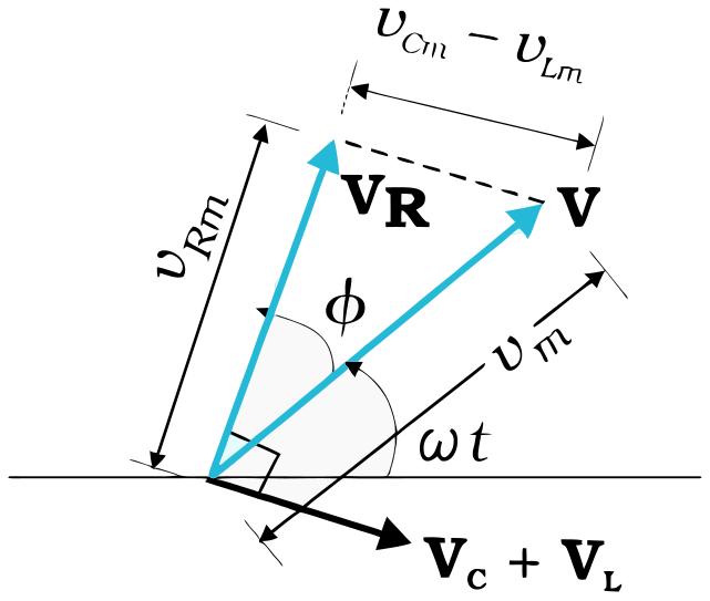
Phase relation for series LCR circuit: $\displaystyle \overrightarrow{\mathrm{V}_{\mathrm{L}}}+\overrightarrow{\mathrm{V}_{\mathrm{R}}}+\overrightarrow{\mathrm{V}_{\mathrm{C}}}=\vec{\mathrm{V}}$
Applying the Pythagorean theorem, we get $\displaystyle v_{m}^{2}=v_{\mathrm{R} m}^{2}+\left(v_{\mathrm{C} m}-v_{\mathrm{L} m}\right)^{2}$
$\displaystyle v_{m}^{2}=\left(i_{m} \mathrm{R}\right)^{2}+\left(i_{m} \mathrm{X}_{\mathrm{C}}-i_{m} \mathrm{X}_{\mathrm{L}}\right)^{2}$
$\displaystyle i_{m}=\dfrac{v_{m}}{\sqrt{\mathrm{R}^{2}+\left(\mathrm{X}_{\mathrm{C}}-\mathrm{X}_{\mathrm{L}}\right)^{2}}}=\dfrac{v_{m}}{\mathrm{Z}}$
where $\displaystyle \mathrm{Z}=\sqrt{\mathrm{R}^{2}+\left(\mathrm{X}_{\mathrm{C}}-\mathrm{X}_{\mathrm{L}}\right)^{2}}$ is the impedance
$\displaystyle \tan \phi=\dfrac{\mathrm{V}_{\mathrm{Cm}}-\mathrm{V}_{\mathrm{Lm}}}{\mathrm{V}_{\mathrm{Rm}}}=\dfrac{\mathrm{X}_{\mathrm{C}}-\mathrm{X}_{\mathrm{L}}}{\mathrm{R}}$ or $\displaystyle \phi=\tan ^{-1}\left(\dfrac{\mathrm{X}_{\mathrm{C}}-\mathrm{X}_{\mathrm{L}}}{\mathrm{R}}\right)$
(b)
(i)
At resonance, i.e. $\displaystyle \mathrm{X}_{C}=\mathrm{X}_{\mathrm{L}}$
(ii)
When the average power consumed is zero.
Alternatively: $\displaystyle \mathrm{P}_{a v g}=\mathrm{V}_{r m s} I_{r m s} \cos \phi$; for $\displaystyle \phi=\pi / 2$, $\displaystyle \cos \phi=0$, therefore $\displaystyle \mathrm{P}_{\text{avg}}=0$
(i)
Principle: It is based on the principle of electromagnetic induction. When the magnetic flux passing through a coil changes continuously, emf is induced.
Working: When the coil is rotated in the magnetic field, the magnetic flux linked with it changes and emf is induced in the coil.
(ii)
Flux linked with a coil at any instant of time, placed in a magnetic field and rotating with angular speed $\displaystyle \omega$: $\displaystyle \phi_{\mathrm{B}}=\mathrm{BA} \cos \omega t$
From Faraday's law $\displaystyle \varepsilon=-N \dfrac{d \phi_{B}}{d t}$
$\displaystyle \varepsilon=N B A \omega \sin \omega t$
(iii)
EMF generated is maximum at $\displaystyle \dfrac{\mathrm{T}}{4}$ and $\displaystyle \dfrac{3 \mathrm{T}}{4}$
All Alternating Current questions2026 question paperNCERT solutions: Alternating CurrentPractice Alternating Current →
More from Alternating Current
- Distinguish between reactance and impedance of an ac circuit. Show that an ideal inductor in an ac circuit does not dissipate any power.2024
- An alternating current is given by I=I_0 cos (100 π) t. The least time the current takes to decrease from its maximum value to zero will be:2025
- A resistor of 30 Ω and a capacitor of 250/(π) μ F are connected in series to a 200 V, 50 Hz ac source. Calculate (i) the current in the circuit, and…2023
- A resistor and an ideal inductor are connected in series to a 100 √2 V, 50 Hz ac source. When a voltmeter is connected across the resistor or the…2024
- A transformer is connected to a 200 V ac source. The transformer supplies 3000 V to a device. If the number of turns in the primary coil is 450, then…2025
- An alternating current I=14 sin (100 π t) A passes through a series combination of a resistor of 30 Ω and an inductor of (2/(5 π)) H. Taking √2=1.4,…2023
- Which of the following statements about a series LCR circuit connected to an ac source is correct?2023
- An inductor, a capacitor and a resistor are connected in series across an ac source of voltage. If the frequency of the source is decreased…2023
CBSE Class 12 Physics past-paper question from the 2026 board exam, with the answer as CBSE’s own marking scheme gives it. Where our answers come from.